Junior network engineer portfolio · Cisco Packet Tracer
Speed run · about 10 minutes · download and go
Lab 03 — Troubleshooting Speed Run: “I Can’t Reach the Website”
A user cannot open a website, but a coworker can. Download the Packet Tracer file, skip the setup, and work the fault from the bottom up: link, IP config, gateway, routed path, name resolution. Each step shows the command, why it is run, what healthy looks like, and what a different result means.
Cisco Packet TracerLayered troubleshootingDNSRouting across a gatewayping and tracertCompTIA Network+
Open lab03-cant-reach-website.pkt in Cisco Packet Tracer (NetAcad). The file is hosted on this site.
The ticket
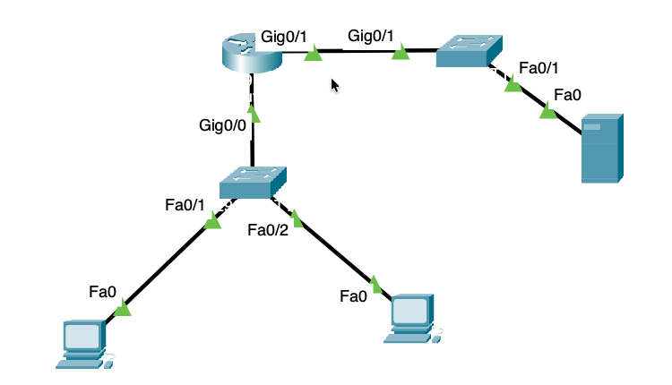
“I can’t get to Instagram from my computer. My coworker can.” You are the helpdesk. The network is already built. Find the fault, fix it, and prove it using the same layered method you would use on a real network.
- Goal: restore access to http://instagram.com from PC1.
- Time: about 10 minutes.
- Rule: change nothing until you can state the cause in one sentence.
This is a speed run. Download the file and skip the setup. If you would rather build the network yourself, the steps are at the bottom of the page.
Quick start: download and go
- 1. Download the Packet Tracer file with the button at the top of the page and open it in Cisco Packet Tracer.
- 2. Switch to Realtime mode (bottom right) so pings return without the animation delay.
- 3. The network is already built and addressed. PC1 is the user with the ticket and PC2 is the coworker.
- 4. If PC1 can already open the site, reset the drill: open PC1, go to the Config tab, set the DNS server to 192.168.20.100, and close the window.
- 5. Open PC1 > Desktop > Command Prompt and start at Step 1 below.
| Device | Role | Address |
|---|---|---|
| PC1 | User with the ticket | 192.168.10.20 |
| PC2 | Coworker, no ticket | 192.168.10.21 |
| R1 | Gateway for both LANs | 192.168.10.1 and 192.168.20.1 |
| SRV1 | DNS and web server | 192.168.20.10 |
The method: bottom up, stop at the first failure
Work the layers in order: link, IP configuration, gateway, routed path, name resolution. Run one test per layer. The first test that fails tells you which layer to fix. Change one thing at a time, then re-run the same test to prove it.
The six steps below are the whole lab. Everything else on the page supports them.
Step 1 · Scope: who is affected?
- Run: Ask who else is affected, or test from a second PC.
- Why: One affected user points to that computer’s settings. Everyone affected points to a shared part: the router, the switch, or the server.
- Healthy: PC2 reaches the site and PC1 does not, so the fault is local to PC1.
- If different: If PC2 fails too, look at the shared parts first: R1, SW1, and SRV1.
Step 2 · Link and IP configuration
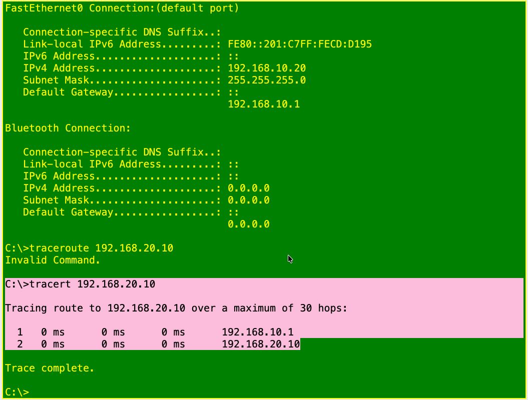
- Run: Check the link light on PC1’s switch port, then run ipconfig /all in PC1’s Command Prompt.
- Why: This confirms layer 1 and that PC1 has a valid address, mask, and gateway before you test anything else.
- Healthy: A green link, IPv4 address 192.168.10.20, mask 255.255.255.0, and default gateway 192.168.10.1.
- If different: An amber or red link means a cable or port problem. An address starting 169.254 means no address was assigned. A wrong mask or gateway breaks traffic to other subnets even when local pings work.
Step 3 · Can PC1 reach its gateway?
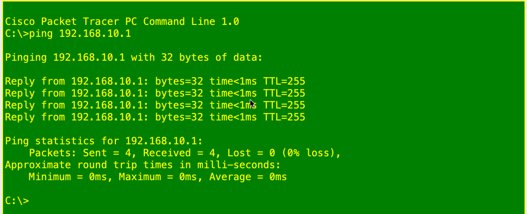
- Run: ping 192.168.10.1
- Why: The gateway is the first hop. If PC1 cannot reach it, nothing beyond it can work.
- Healthy: Four replies with TTL 255, which is the router answering.
- If different: Timeouts mean the fault is on the user LAN or R1’s interface. Stop and fix layers 1 to 3 before you look at DNS.
Step 4 · Can PC1 reach the server across the router?
- Run: ping 192.168.20.10, then tracert 192.168.20.10
- Why: This proves the routed path and the server in one step, so you can rule routing in or out.
- Healthy: Replies with TTL 127 from the server, and a trace that shows two hops: 192.168.10.1, then 192.168.20.10.
- If different: If the gateway ping passed but this one fails, look at R1’s server-side interface, the route, SW2, or SRV1. A trace that stops at hop 1 points at R1. A trace that stops after hop 1 points at the server side.
The first ping can drop a packet while ARP resolves. Run it twice before you decide it failed.
On Windows the command is tracert. Typing traceroute returns “Invalid Command.”
Step 5 · Can PC1 resolve the name?
- Run: ping instagram.com, then check the DNS server in ipconfig /all or on PC1’s Config tab.
- Why: If Step 4 passed, the network path is good. A failure by name points to name resolution.
- Healthy: The ping reads “Pinging 192.168.20.10” and replies. The name was translated to the server’s address, and the DNS server setting is 192.168.20.10.
- If different: If Packet Tracer reports it could not find the host while Step 4 passed, the problem is DNS. Here PC1’s DNS server is 192.168.20.100, an address nothing answers on.
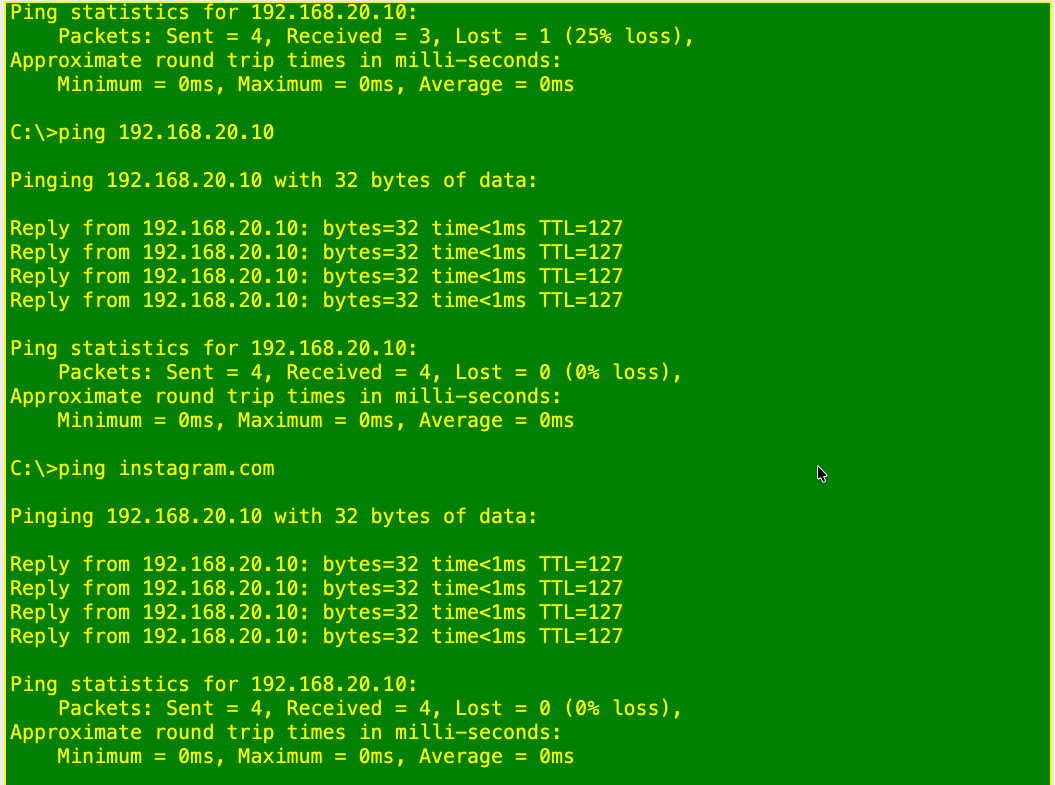


Key phrase: “Pings by IP work, pings by name fail, so DNS.”
Step 6 · Fix it and prove it
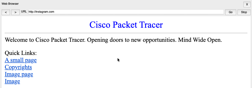
- Run: Set PC1’s DNS server to 192.168.20.10 on the Config tab, then run ping instagram.com and open http://instagram.com in the Web Browser.
- Why: Re-run the exact test that failed. Never close the ticket on a guess.
- Healthy: Replies from 192.168.20.10 and the page loads.
- If different: If the name resolves but the page will not load, DNS is fixed and the next place to look is the HTTP service on SRV1 (Services > HTTP).
What you see and what it means
| What you see | What it means | Where to look |
|---|---|---|
| Link light amber or red | Layer 1 or port problem | Cable, port, switch |
| Address starts with 169.254 | No address was assigned | PC’s IP settings |
| Gateway ping times out | User LAN or gateway problem | SW1 port, R1 Gi0/0, PC1 gateway and mask |
| Gateway ping works, server ping times out | Problem beyond the gateway | R1 Gi0/1, routing, SW2, SRV1 |
| Both pings work, name fails | Name resolution | PC1’s DNS server setting, then the DNS service on SRV1 |
| Name resolves, page will not load | Web service problem | HTTP service on SRV1 |
| More than one user fails | Shared component | R1, SW1, or SRV1 |
Say it out loud: the 30-second version
“I’d start by confirming scope. Is it one user or the whole site? One user points to a local setting, not an outage. Next I’d check the link and the IP config. Then I’d test in layers: can it reach its gateway, and can it reach the server by IP across the router? If the IP path works and the name doesn’t resolve, that’s DNS, not routing. Then I’d fix the setting, verify with the same test that failed, and document what I found.”
Troubleshooting log for this run
| Field | Entry |
|---|---|
| Symptom | PC1 cannot open instagram.com. A coworker can. |
| What I checked, in order | Scope, link and IP config, gateway ping, server ping and tracert, name ping, DNS setting. |
| Root cause | PC1’s DNS server was 192.168.20.100, which does not exist on the server subnet. |
| Fix | Set PC1’s DNS server to 192.168.20.10. |
| How I verified it | Re-ran ping instagram.com and loaded http://instagram.com. |
| What I would check first next time | The DNS server setting on the PC, right after confirming the IP path works. |
Design notes: why the server is on its own switch and subnet
Real networks keep servers apart from user desks. A server on its own switch means a user-side problem does not take the server down. A server on its own subnet means traffic to it crosses the router, so the DNS check in this lab also tests routing.
In an enterprise environment, DNS and web hosting would run on separate servers, so a DNS outage and a web outage can be told apart by which one fails. This lab combines them on SRV1 to keep the topology small.
Network+ concepts demonstrated
- DNS: name-to-address resolution, and why a PC with a bad DNS server can reach an IP but not a name.
- Layered troubleshooting: link, IP config, gateway, routed path, name resolution, in that order.
- TTL: 255 from the router and 127 from the server, a quick way to tell which device answered.
- ICMP and tracert: echo replies, timeouts, and hop-by-hop path testing.
- Verification: repeating the exact test that failed.
Optional: build the environment yourself
Skip this if you downloaded the file. Building the network takes about 10 minutes.
| Device | Interface | IP address | Mask | Gateway | DNS |
|---|---|---|---|---|---|
| R1 (Cisco 2911) | Gi0/0 | 192.168.10.1 | 255.255.255.0 | – | – |
| R1 | Gi0/1 | 192.168.20.1 | 255.255.255.0 | – | – |
| SRV1 (Server-PT) | Fa0 | 192.168.20.10 | 255.255.255.0 | 192.168.20.1 | itself |
| PC1 (PC-PT) | Fa0 | 192.168.10.20 | 255.255.255.0 | 192.168.10.1 | 192.168.20.10 |
| PC2 (PC-PT) | Fa0 | 192.168.10.21 | 255.255.255.0 | 192.168.10.1 | 192.168.20.10 |
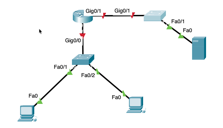
- SW1 and SW2 are Cisco 2960-24TT switches. SW1 is the user switch and SW2 is the server switch.
- All cables are copper straight-through.
- PC1 Fa0 to SW1 Fa0/1, and PC2 Fa0 to SW1 Fa0/2.
- R1 Gi0/0 to SW1 Gi0/1 (user LAN, 192.168.10.0/24).
- R1 Gi0/1 to SW2 Gi0/1 (server LAN, 192.168.20.0/24).
- SRV1 Fa0 to SW2 Fa0/1.
Configure R1 from its CLI tab. If Packet Tracer offers the initial configuration dialog, answer no.
enable
configure terminal
hostname R1
interface GigabitEthernet0/0
 description User LAN - to SW1 Gi0/1
 ip address 192.168.10.1 255.255.255.0
 no shutdown
 exit
interface GigabitEthernet0/1
 description Server LAN - to SW2 Gi0/1
 ip address 192.168.20.1 255.255.255.0
 no shutdown
 exit
end
show ip interface brief
Router ports are administratively down by default, so no shutdown is required. Both ports should read up and up.
- SRV1: set the static address from the table. In Services, turn DNS on and add an A record for instagram.com pointing to 192.168.20.10. Keep HTTP on with index.html present.
- PC1 and PC2: set static addresses from the table, with DNS 192.168.20.10.
- Baseline check from PC1: ping 192.168.10.1, ping 192.168.20.10, ping instagram.com, then open http://instagram.com. All four should work before you break anything.
- To start the drill, set PC1’s DNS server to 192.168.20.100.