Junior network engineer portfolio · Cisco Packet Tracer
Part 1 of 2 · static routing + DHCP relay (Miami lease test in progress)
Lab 02 — Centralized DHCP with Relay Agents
Three sites joined by /30 point-to-point links. Miami and New York have no local DHCP server: each city router relays DHCP requests across the WAN to a server in the data center. Covers DORA, giaddr, scopes, static routing, and a real troubleshooting log.
Cisco Packet TracerDHCP relay (ip helper-address)Subnetting /26 and /30Static routingCompTIA Network+
Open lab02-dhcp-relay.pkt in Cisco Packet Tracer (NetAcad). The file is hosted on this site.
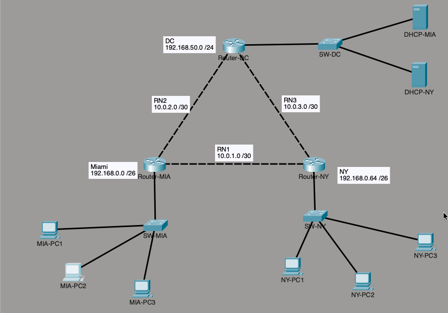
Scenario and design goals
A company has a data center (DC) and two branch cities, Miami and New York. Each branch LAN needs its addresses assigned automatically, but the DHCP servers live in the data center so administration stays in one place.
- Three Cisco routers: Router-DC, Router-MIA, and Router-NY, joined in a triangle by /30 links.
- Two DHCP servers on the DC LAN: 192.168.50.10 serves Miami and 192.168.50.20 serves New York.
- Each branch router acts as a DHCP relay agent for its LAN.
- Routing is static in this part. Dynamic routing is Part 2.
Why a relay is needed: a PC with no address sends a DHCP Discover as a broadcast. Routers do not forward broadcasts, so the request would die at the branch router. The relay agent (ip helper-address) catches it and forwards it as a unicast to the server.
Addressing plan
| Network | Subnet | Notes |
|---|---|---|
| Miami LAN | 192.168.0.0/26 | Gateway 192.168.0.1 (Router-MIA Gi0/0/0) |
| New York LAN | 192.168.0.64/26 | Gateway 192.168.0.65 (Router-NY Gi0/0/0) |
| DC LAN | 192.168.50.0/24 | Gateway 192.168.50.1 (Router-DC Gi0/0/0); servers at .10 and .20 |
| MIA – NY link | 10.0.1.0/30 | MIA .1, NY .2 |
| MIA – DC link | 10.0.2.0/30 | MIA .1, DC .2 |
| NY – DC link | 10.0.3.0/30 | NY .1, DC .2 |
A /30 has four addresses and two usable, which is exactly what a point-to-point router link needs. A /26 gives each city 62 usable hosts and splits 192.168.0.0/24 into clean 64-address blocks.
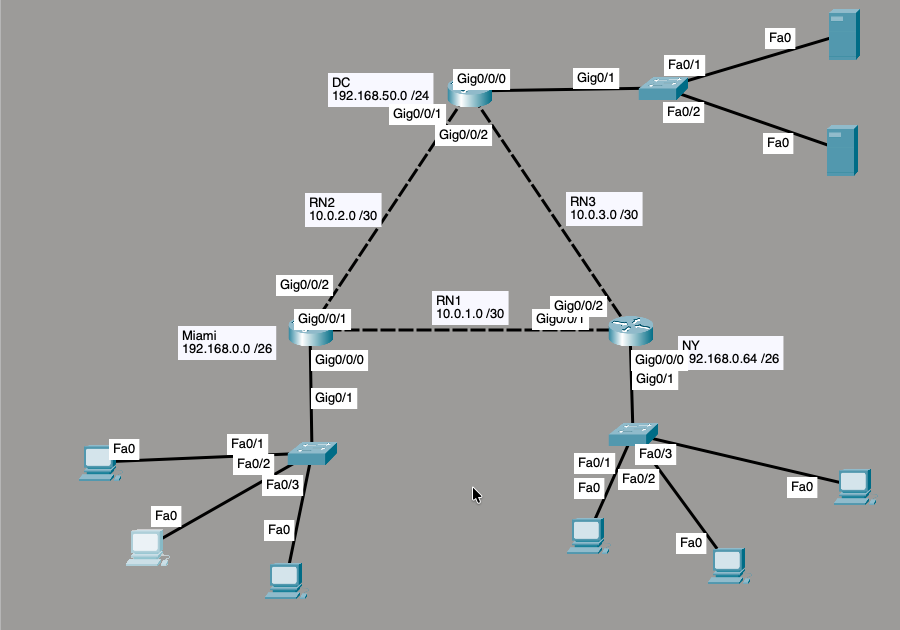
| From | Port | To | Port |
|---|---|---|---|
| Router-DC | Gig0/0/0 | SW-DC | Gig0/1 |
| Router-DC | Gig0/0/1 | Router-MIA | Gig0/0/2 |
| Router-DC | Gig0/0/2 | Router-NY | Gig0/0/2 |
| Router-MIA | Gig0/0/1 | Router-NY | Gig0/0/1 |
| Router-MIA | Gig0/0/0 | SW-MIA | Gig0/1 |
| Router-NY | Gig0/0/0 | SW-NY | Gig0/1 |
Devices: three Cisco ISR4331 routers, three 2960-24TT switches, six PC-PT hosts (three per city), and two Server-PT DHCP servers. Router-to-router links are dashed in the diagram (RN1, RN2, RN3).
How a relayed lease works
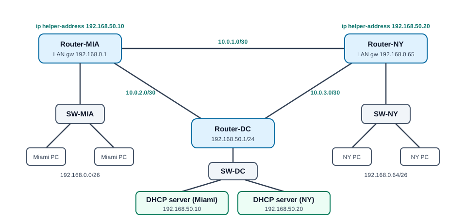
- Discover: the client broadcasts (UDP 68 to UDP 67) because it has no address yet.
- Relay: the city router receives it, writes its own LAN interface address into the giaddr field, and forwards the request as a unicast to the helper address.
- Offer: the server compares giaddr to its scopes, picks the one that matches that subnet, and replies to the relay, which delivers it to the client.
- Request and Acknowledge: the exchange finishes through the same relay and the client keeps the lease.
The relay only works if routing works in both directions. The Discover can reach the server and the Offer still gets lost without a return route.
DHCP server configuration
New York DHCP server (192.168.50.20, gateway 192.168.50.1):
| Setting | Value |
|---|---|
| Pool name | Desktops NY |
| Default gateway | 192.168.0.65 (the New York LAN interface) |
| DNS server | 192.168.50.20 |
| Start IP address | 192.168.0.70 |
| Subnet mask | 255.255.255.192 |
| Maximum users | 57 |
Scope math: the New York usable range is .65 to .126 (62 addresses). The first five (.65 to .69) are held back for the gateway and infrastructure, so the pool starts at .70 and serves 57 hosts. The server uses the gateway field for the client's default gateway, so it points at the branch router, not the DC router. The Miami server (192.168.50.10) follows the same pattern with gateway 192.168.0.1.
Terminal commands
Commands in the order I used them. Each router starts at user mode; enable moves to privileged mode and configure terminal enters global configuration. Router prompts show the mode: > is user, # is privileged, (config)# is global configuration, and (config-if)# is interface configuration.
Router-DC (data center gateway for the servers):
enable
configure terminal
hostname Router-DC
no ip domain-lookup
interface GigabitEthernet0/0/0
 description Connected to SW-DC
 ip address 192.168.50.1 255.255.255.0
 no shutdown
 exit
interface GigabitEthernet0/0/1
 description Connected to Router-MIA
 ip address 10.0.2.2 255.255.255.252
 no shutdown
 exit
interface GigabitEthernet0/0/2
 description Connected to Router-NY
 ip address 10.0.3.2 255.255.255.252
 no shutdown
 exit
ip route 192.168.0.0 255.255.255.192 10.0.2.1
ip route 192.168.0.64 255.255.255.192 10.0.3.1
end
write memory
Router-MIA (Miami gateway and DHCP relay):
enable
configure terminal
hostname Router-MIA
no ip domain-lookup
interface GigabitEthernet0/0/0
 description Connected to SW-MIA
 ip address 192.168.0.1 255.255.255.192
 ip helper-address 192.168.50.10
 no shutdown
 exit
interface GigabitEthernet0/0/1
 description Connected to Router-NY
 ip address 10.0.1.1 255.255.255.252
 no shutdown
 exit
interface GigabitEthernet0/0/2
 description Connected to Router-DC
 ip address 10.0.2.1 255.255.255.252
 no shutdown
 exit
ip route 192.168.0.64 255.255.255.192 10.0.1.2
ip route 192.168.50.0 255.255.255.0 10.0.2.2
end
write memory
Router-NY (New York gateway and DHCP relay):
enable
configure terminal
hostname Router-NY
no ip domain-lookup
interface GigabitEthernet0/0/0
 description Connected to SW-NY
 ip address 192.168.0.65 255.255.255.192
 ip helper-address 192.168.50.20
 no shutdown
 exit
interface GigabitEthernet0/0/1
 description Connected to Router-MIA
 ip address 10.0.1.2 255.255.255.252
 no shutdown
 exit
interface GigabitEthernet0/0/2
 description Connected to Router-DC
 ip address 10.0.3.1 255.255.255.252
 no shutdown
 exit
ip route 192.168.0.0 255.255.255.192 10.0.1.1
ip route 192.168.50.0 255.255.255.0 10.0.3.2
end
write memory
Fixing a bad static route (the exact commands I used for the 194.168 and 193.168 typos):
configure terminal
no ip route 194.168.50.0 255.255.255.0 10.0.2.2
ip route 192.168.50.0 255.255.255.0 10.0.2.2
end
write memory
Changing the relay target on an interface:
configure terminal
interface GigabitEthernet0/0/0
 no ip helper-address 192.168.50.20
 ip helper-address 192.168.50.10
 end
write memory
Verification and troubleshooting commands on the routers:
| Command | What it shows |
|---|---|
| show running-config | Current config, including interface addresses, helper addresses, and static routes |
| show startup-config | Saved config, to confirm write memory worked |
| show ip interface brief | Every interface with its IP address and up/up status |
| show ip route | Routing table: C and L for connected networks, S for static routes |
| show arp | IP-to-MAC mappings the router has learned, such as a leased PC address |
| ping <address> | ICMP echo test; add repeat 5 to send five packets |
| Ctrl+Shift+6 | Aborts a ping or other command that is hanging |
Commands on the PCs (Desktop > Command Prompt) and servers:
| Command | What it shows |
|---|---|
| ipconfig /all | Leased address, mask, gateway, DHCP server, and DNS server |
| ipconfig /release then ipconfig /renew | Drops the lease and requests a new one through the relay |
| ping -n 4 <address> | Sends four ICMP echoes (use Ctrl+C to stop a hung ping) |
| tracert <address> | Hop-by-hop path, which shows each router crossed |
| arp -a | The PC's ARP table, which proves Layer 2 reachability to the gateway |
Server steps (Desktop > Config and Services > DHCP in Packet Tracer): set the static IP, mask, gateway, and DNS under FastEthernet0; turn the DHCP service on; fill in the pool name, default gateway, DNS, start address, mask, and maximum users; then click Save. The scope is not active until it is saved.
Verification
| Check | Expected | Result |
|---|---|---|
| show ip interface brief (MIA, NY, DC) | All used interfaces up/up | PASS |
| show ip route (Router-DC) | Connected 192.168.50.0/24 and both /30 links, plus static routes to both city LANs | PASS |
| Router-MIA → ping 192.168.50.1 | Replies across the MIA–DC link (first packet may drop while ARP resolves) | PASS (4/5, then 5/5) |
| New York PC → ipconfig /all | Address from the NY pool, gateway .65, DHCP server .20, DNS .20 | PASS (192.168.0.70) |
| New York PC → ping 192.168.0.65 | Replies | PASS (4/4, TTL 255) |
| Router-NY → show arp | PC's MAC listed for its leased address | PASS |
| Router-NY → ping 192.168.0.70 | Replies | PASS (5/5) |
Still to verify in this part: a Miami PC lease from 192.168.50.10, plus cross-site pings and traceroutes between the city gateways.
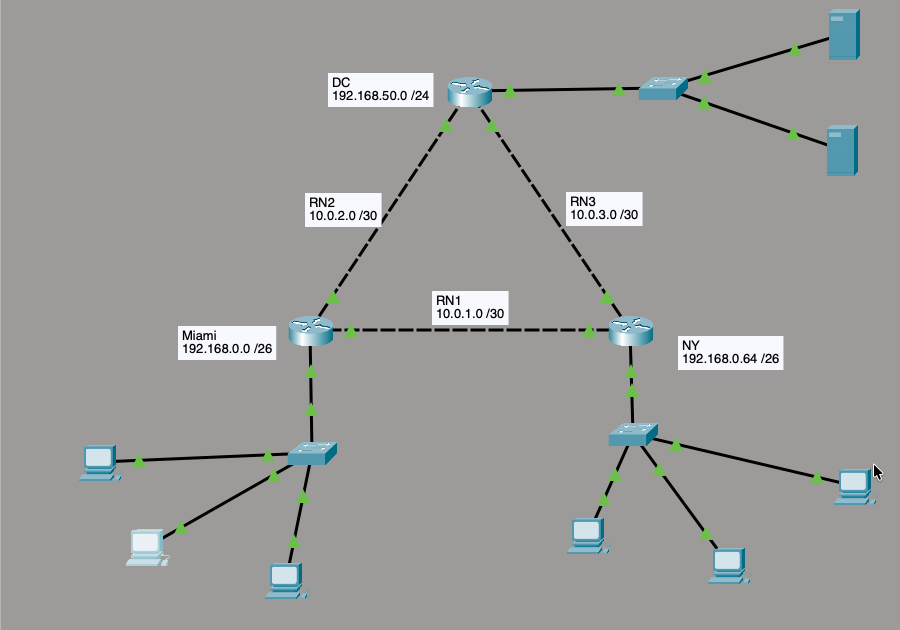
Troubleshooting log
| Symptom | What I checked | Root cause | Fix |
|---|---|---|---|
| Miami could not reach the DHCP server's subnet | show running-config, show ip route | Static route typed as 194.168.50.0 instead of 192.168.50.0 | Removed it and added ip route 192.168.50.0 255.255.255.0 10.0.2.2 |
| New York had no route back to the Miami LAN | show ip route showed S 193.168.0.0/26 | Another octet typo: 193.168.0.0 instead of 192.168.0.0 | no ip route 193.168.0.0 ..., then ip route 192.168.0.0 255.255.255.192 10.0.1.1 |
| Pings on PCs and routers hung for 10+ seconds | arp -a and show arp showed Layer 2 working | Packet Tracer was in Simulation mode, which animates every packet | Switched to Realtime mode; pings returned instantly |
| Destination host unreachable from 192.168.0.65 | Re-read the command and the reply source | I had typed 192.168.0.6 instead of 192.168.0.65; the gateway answered, proving Layer 3 worked | Retyped the address |
Method: identify the problem, form a theory, test it, fix it, verify, and document. Reading the ARP tables on both ends ruled out Layer 2 before I went looking for the real cause.
Network+ concepts covered
- DHCP and DORA (Discover, Offer, Request, Acknowledge), scopes, leases, and the gateway and DNS options a server hands out.
- DHCP relay and giaddr, and why a router is the boundary of a broadcast domain.
- UDP port 67 (server) and 68 (client). A client that cannot reach a server falls back to an APIPA address in 169.254.0.0/16.
- Subnetting: /26 for LANs and /30 for point-to-point links, with usable ranges and broadcast addresses.
- Static routing, and how one wrong octet breaks reachability.
- ARP (IP to MAC), ICMP echo and destination unreachable, TTL (IOS routers reply with TTL 255), and traceroute.
- The troubleshooting methodology, plus interface descriptions and saved configs as documentation habits.
Key takeaways
- A relay needs routes in both directions, not just toward the server.
- The server picks a scope from the relay's interface subnet, so every scope must match a real LAN.
- Save the pool on the server after editing it; an unsaved scope looks right on screen but serves nothing.
- Check the tool before the network: Simulation mode looked like an outage.
- Read unreachable replies carefully. The source address shows which device gave up.
Part 2 replaces the static routes with dynamic routing and repeats the same verification. This was built as part of my Enterprise Cloud Computing coursework; the troubleshooting and verification are my own work. Lab passwords, where used, are for lab use only, never production.